Scale in any design program is one of the most important terms, one of the most important characteristics of the visual presentation of a drawing and one of the most frequently used operations. AutoCAD has a whole scale management system, but before deciding how to increase the scale of a drawing in AutoCAD or how to reduce it, you need to be very clear about why this is done and in what mode of the program itself.

Contents
Scaling Basics in AutoCAD
Therefore, to begin with, let’s define the fundamental points of scaling in this application.
Firstly, such a completely justified, extremely simple and natural idea of work has been adopted – all sizes are presented here “one to one.” It is enough just to set the unit of measurement and set the “drawing limits” in the set units. If this is a building project, then, say, in millimeters, 10,000 by 20,000, and then build all the objects according to these dimensions, which go “from the terrain.” It is very convenient, you do not need to scale all these dimensions “in your head” to reduce and transfer objects to paper, as designers did in the good old days with pencils in their hands at drawing boards. This greatly speeds up the development process and makes it more natural.
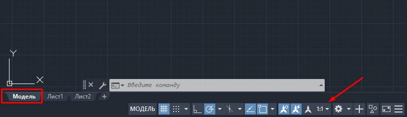
Secondly. The screen, of course, is not rubber, and the same 10,000 by 20,000 mm. on the screen in pixels, of course, one-to-one will not be displayed. So we get the first case of solving the problem of how to change the scale in AutoCAD – for a convenient visual presentation of the drawing on the screen, so that from time to time some of its details can be made more accessible for analysis and work. We do this work in the “Models” mode.
Thirdly. The scale of the drawing in practice is more related to its printed form. This can be done in two ways – either by already indicating the scale immediately before printing, which must be recognized as not a very good idea of the developers themselves (you can recall the sacramental from Munchausen – “not all that glitters is gold”), or by indicating the scale of the view in the “Leaf” mode … Here it is only very important for oneself to accept the ideology of the work on which the program rests:
- All development should be done in the “Models” mode.
- All preparation of the printed form of development, including additional tables of specifications, including the same frames – this is the prerogative of the “Sheet” mode.
- Tables and frames can be created in the “Model”, development, drawing can be carried out in the “List”, but if these operations are really performed, then nothing else but a lack of understanding of the essence of AutoCAD, this cannot be called – this mixing is not otherwise akin to “mixing God’s gift and scrambled eggs “, and in fact, and in another case.

Now that these preliminary remarks have been made about changing the scale of the drawing in AutoCAD, you can proceed to the analysis of all the scaling techniques.
Changing the scale of the visual representation on the screen – “Model” mode
So, we work strictly according to real dimensions and depict all objects “one to one”. But it will be necessary from time to time to remove the working area or bring it closer. A whole system of tools is intended for this. All of them are collected either in the “Zoom” toolbar (not displayed by default, but available through the “Tools” / “Toolbars” menu) or through the drop-down list of the “Zoom Window” button, which is initially already on the screen, on the main toolbar.

It goes without saying that it is more convenient to use a list. Displaying the panel is inconvenient for two simple reasons:
- and everything you want on the screen will not fit, and AutoCAD is already full of useful tools, the competition among them for a permanent place is very high;
- and you shouldn’t “pollute” the screen with unnecessary buttons, to which there are other ways of access.
When starting serious work in the AutoCAD system, everyone, of course, must establish their own discipline of work in this program, both globally and locally. In particular, which scaling tools to use, which are the most understandable and appropriate.
But one tool – “Zoom Realtime” – seems to be used by everyone. This is real-time scaling. You just choose the tool. In this case, the mouse turns into a “magnifying glass” with a minus sign in the 3rd quadrant around the “magnifying glass” and with a plus sign in the 1st quadrant. Now, moving the mouse down – to the left, we decrease the scale, moving it up – to the right, we increase it.

Since such a simple solution to the question of how to adjust the scale in AutoCAD is used very often, initially this tool is already in the main toolbar – to the left of the button with a drop-down set of scaling commands.
You have to set the scale often, and you also often have to adjust “further”, decreasing, increasing, returning to the previous view. In order not to remember what scale was the previous one, there is also a special button – “Zoom Previous” – a transition to the previous scale.
The system of the main commands for changing the scale in AutoCAD consists of the following set:
- Zoom window – setting the scale by specifying the “describing” a fragment of the window, the tool requires skill in working and understanding the ratio of the resulting scale and the size of the window itself, it is often much easier to simply apply the RealTime change;
- Zoom dynamic – changing the scale “in dynamics” so that the area that falls into this rectangle is displayed as much as possible on the screen, while the entire drawing is first displayed on the screen and using the rectangle (the size of which is also set by the user), you can specify the required area;
- Zoom scale – specifying the scale by a number in the command line: “2” – doubled; “0.5” – halve;
- Zoom center – setting the scale by the center and radius – also requires skill and can be successfully replaced with realtime;
- Zoom in – increases the scale;
- Zoom out – define the scale to decrease;
- Zoom all – the scale is automatically selected so that the entire drawing fits on the screen within its established limits, if some objects go beyond the limits (which is absolutely not worth doing), then this tool makes it so that all objects fall on the screen;
- Zoom extends – select the largest possible scale, but so that all objects fit on the screen.
All these tools can, one way or another, find their place in real practice. But, as experience shows, the most used are Realtime, All and Window. Often these three are enough.

A few more notes
Changing the scale, we often shift the visual representation of the drawing – the desired place is not in the center or even “ran away” off the edge of the screen. In this situation, the Pan Realtime tool helps a lot to move everything to the center – it is always in the set on the main panel.
The exclusive function of AutoCAD is the ability to split the screen into several viewports, each window can have its own section of the same drawing. So, each viewport (this is the terminology of the program itself) can have its own scale, which makes the idea of viewports especially valuable.
When working with complex drawings, it is often necessary to have a general view on the screen constantly before your eyes, while working with some “trifle”. A special window is intended for this – “Aerial View”. The window allows you to constantly see the entire development and is available through the menu “View” / “Aerial View”. A very useful feature, but … for large screens. Here at “29 inches” it is very good, at “17” it only clutters the screen, but it doesn’t hurt to remember about it in any case.

Scaling directly when adjusting print settings
And again we come to the need to understand the “internal” motives that drove the developers of AutoCAD. Without their understanding, the success of serious use of this program is very doubtful.
This is directly related to the scaling of the drawing for printing. As a matter of fact, all such settings are intended to be performed by the “Sheet” mode. But, of course, when setting up the printing itself, this can be done when the corresponding window is already called by “Ctrl + P” (this, of course, hot keys, the tool itself is in the “File” / “Plot” menu, although there is more “narrow” – “File” / “Page Setup”). But why, the question arises.

In any case, there is a group of settings “Plot Scale” that will help you map the units of the drawing to the “millimeters” on paper. Moreover, you can set a specific area that will be printed, make a choice from more than two dozen fixed scales to increase or decrease.
In any case, you need to understand that working with these settings requires skill and experience in accurately correlating the sizes of the selected sheet of paper and the sizes of the objects themselves in the completed project.
Scaling in “Sheet” mode
The real benefits of scaling can be felt precisely in the “Sheet” mode, when views of the completed project are prepared for printing on a layout of a real sheet. Actually, all the scaling techniques in this mode, one to one, coincide with the techniques of the model mode, taking into account one extremely important point: it is also possible (and necessary, and necessary) to create views on the “Sheet”, these views:
- floating – all over the sheet (as opposed to views in the “Models” mode);
- can overlap – also, unlike the “Model”, it is better to avoid the use of overlapping views, but often you simply cannot do without this feature, especially if you take into account that views can have an arbitrary shape;
- can have different scales – an indispensable feature (as in the “Model” mode).

Please note that when working with the presented tools in the “Sheet” mode, it is very important to pre-select a working view. If the view is not selected, the work is done with the sheet as a whole for its visual presentation.
In any case, practice and careful tracking of the order of operation of each tool will help to understand the functioning of each tool. They are not all used equally, usually for printing we need fixed standard scales, this tool is in use – “Zoom Scale”. But look at others as well.
There is another very interesting detail hidden in these tools – they are able to “teach” this program, understanding the processes of its operation and the laid down rules for the electronic presentation of drawings – a fascinating lesson for curious people, ready to search and experiment.